4. Assembling the Flight Computer
You are ready to begin assembly after you have had the PCB fabricated and printed the custom components. Both sizes of the Flight Computer require the battery holder and the external interface (body, face, and panel parts). If you are assembling a standard Flight Computer, you will also need the breadboard clip.
The assembly of both the standard and mini Flight Computers is nearly identical. This guide describes the process for the standard version.
4.1. Main PCB Assembly
- Solder all the resistors, headers, screw terminals, and the male IDC header to the board. Starting with the shortest pieces (the resistors) and progressively attaching taller parts seems to work well. When you are done, it should look like the board shown in Fig. 1.
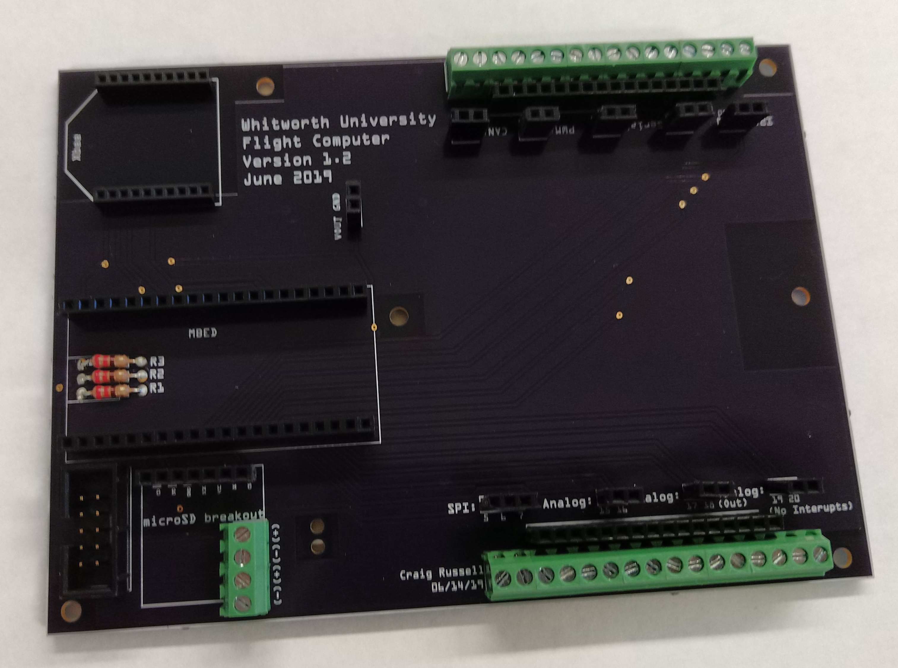
Fig. 1. PCB after all of the electronic components have been soldered.
- Place the LiPo battery into the battery holder, with the wires coming out the notch on the side of the holder. Next, run the power and ground connections through the pair of holes in the PCB, as shown in Fig. 2. Secure the wires in the screw terminals next to the SD card reader headers (the two closest to the header). The black wire goes to terminal with a minus sign, and the red wire goes to the terminal with a plus sign.
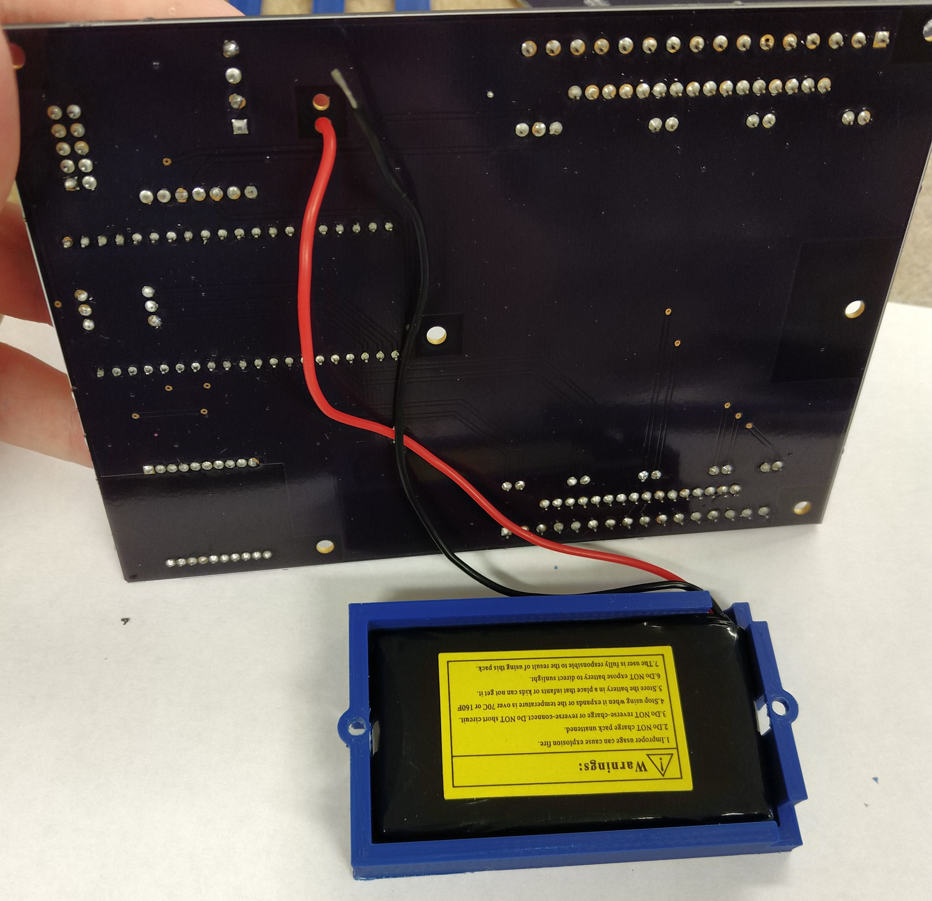
Fig. 2. LiPo battery in holder. The LiPo wires pass through a pair of holes in the PCB located near a screw terminal block on the opposite side.
- Using 5/16-inch #4-40 screws and appropriate nuts, secure the battery holder to the bottom of the PCB. The nuts should fit tightly into the battery holder and not rotate while the screws are tightened. Similarly, if assembling a standard Flight Computer, attach the breadboard clip to the top of the PCB, as shown in Fig. 3.
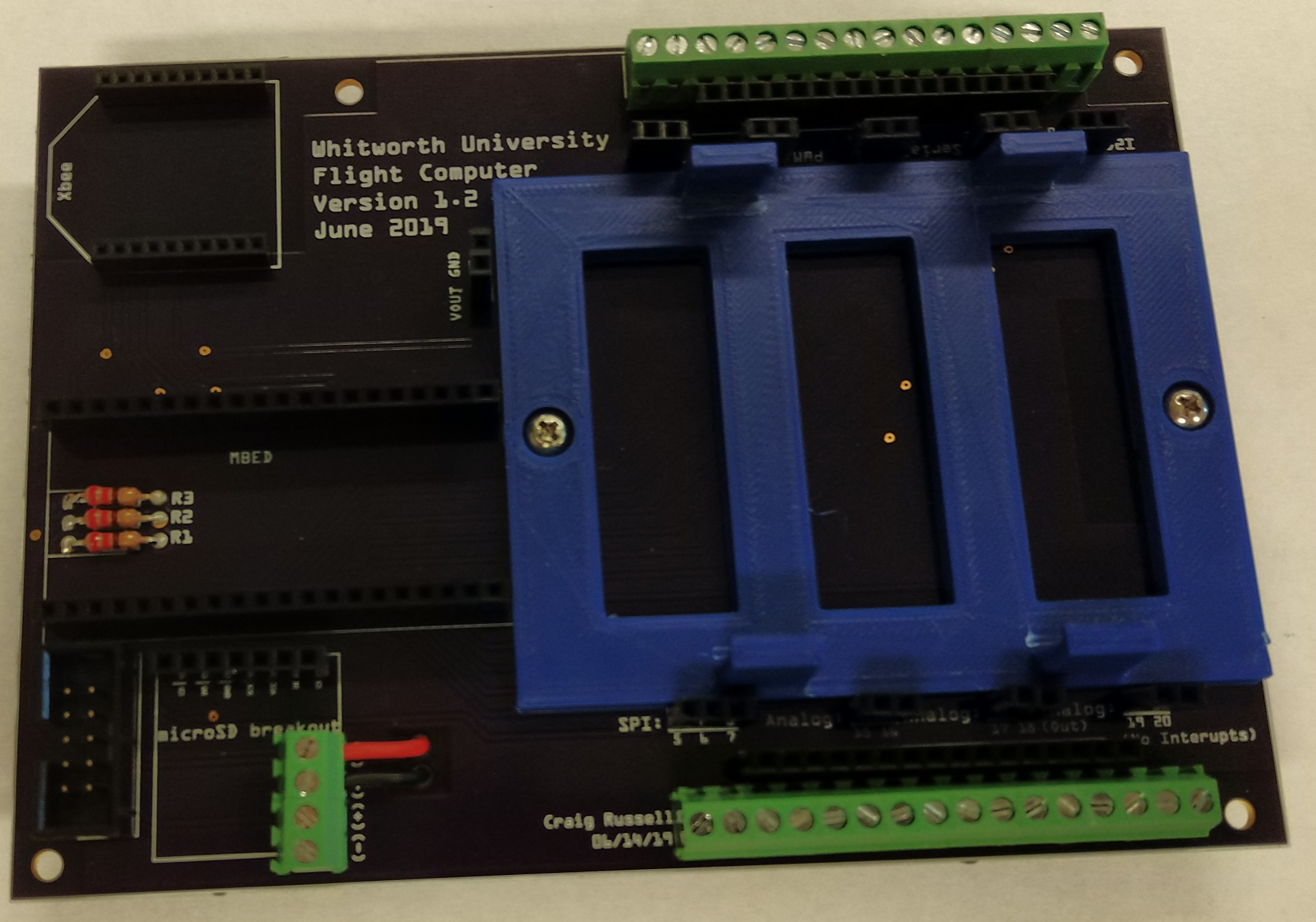
Fig. 3. PCB with breadboard clip secured and battery wires connected to screw terminals.
- Carefully snap a breadboard into the breadboard clip. It is best to place one side under the clips, then force the other side down until it snaps in.
- The charging adapter needs to be attached to the remaining screw terminals near the SD card reader header. The black wire is attached to the minus terminal nearest the edge of the board and the red wire is to the positive terminal next to it, as shown in Fig. 4.
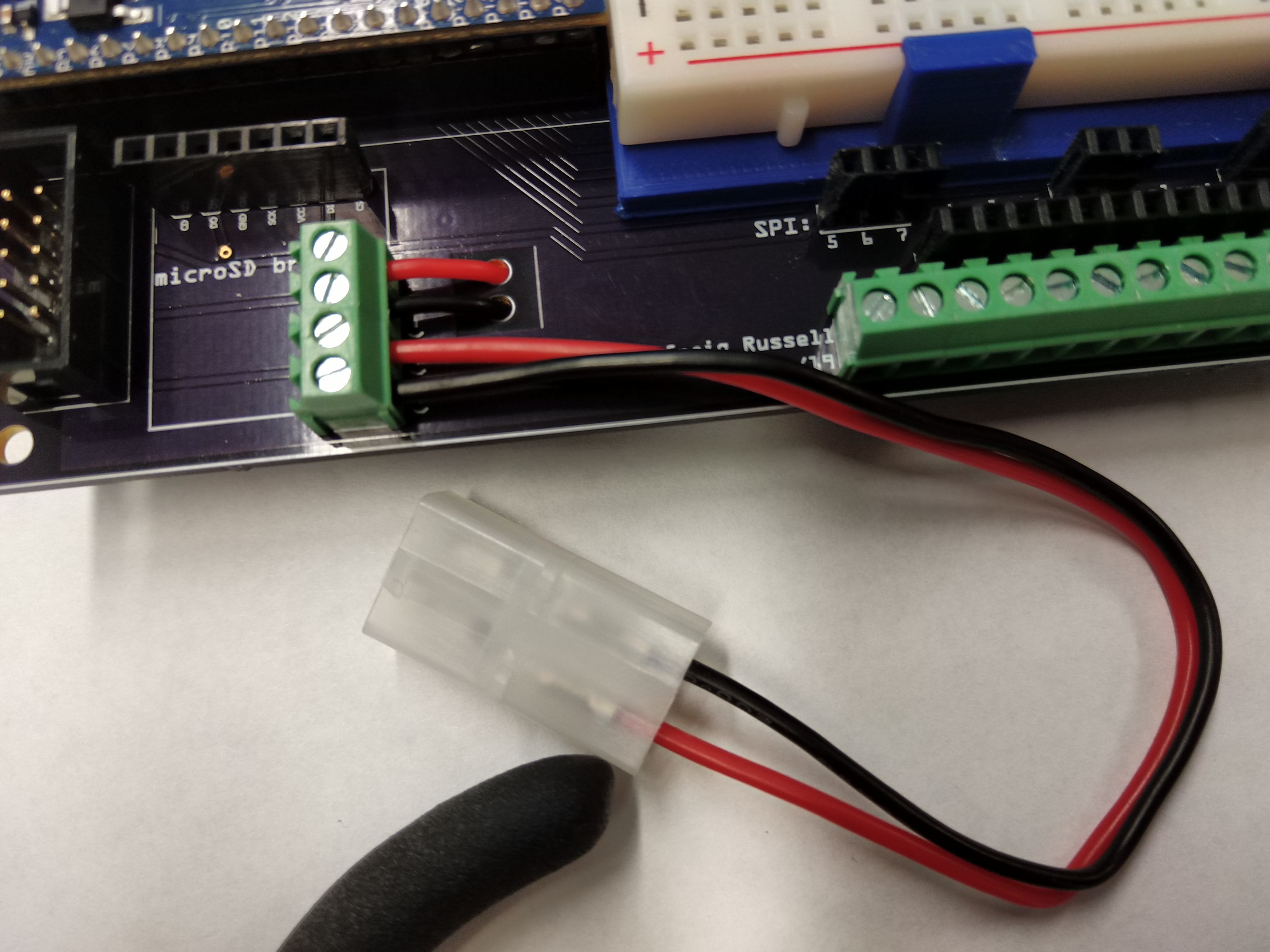
Fig. 4. Charging adapter connected to the two screw terminals closest to the edge of the PCB. The wires from the battery are connected to the other terminals.
4.2. External Interface Assembly
- The external interface consists of three 3D printed parts: the body, the face, and the panel. You will also need a 2 hole by 5 hole rectangle of perforated board to hold components in place inside of the interface.
- Solder short lengths (2-3 inches) of wire to each lead of the DPST switch. Use shrink tube to cover the solder joints and reduce the amount of bare metal visible.
- Place the switch into the slot in the interface face, along with the three LEDs (see Fig. 5). When placing the LEDs, it works best to align them so that the two leads are perpendicular to the long edges of the face, with the three ground leads (the shorter legs) on the same side.
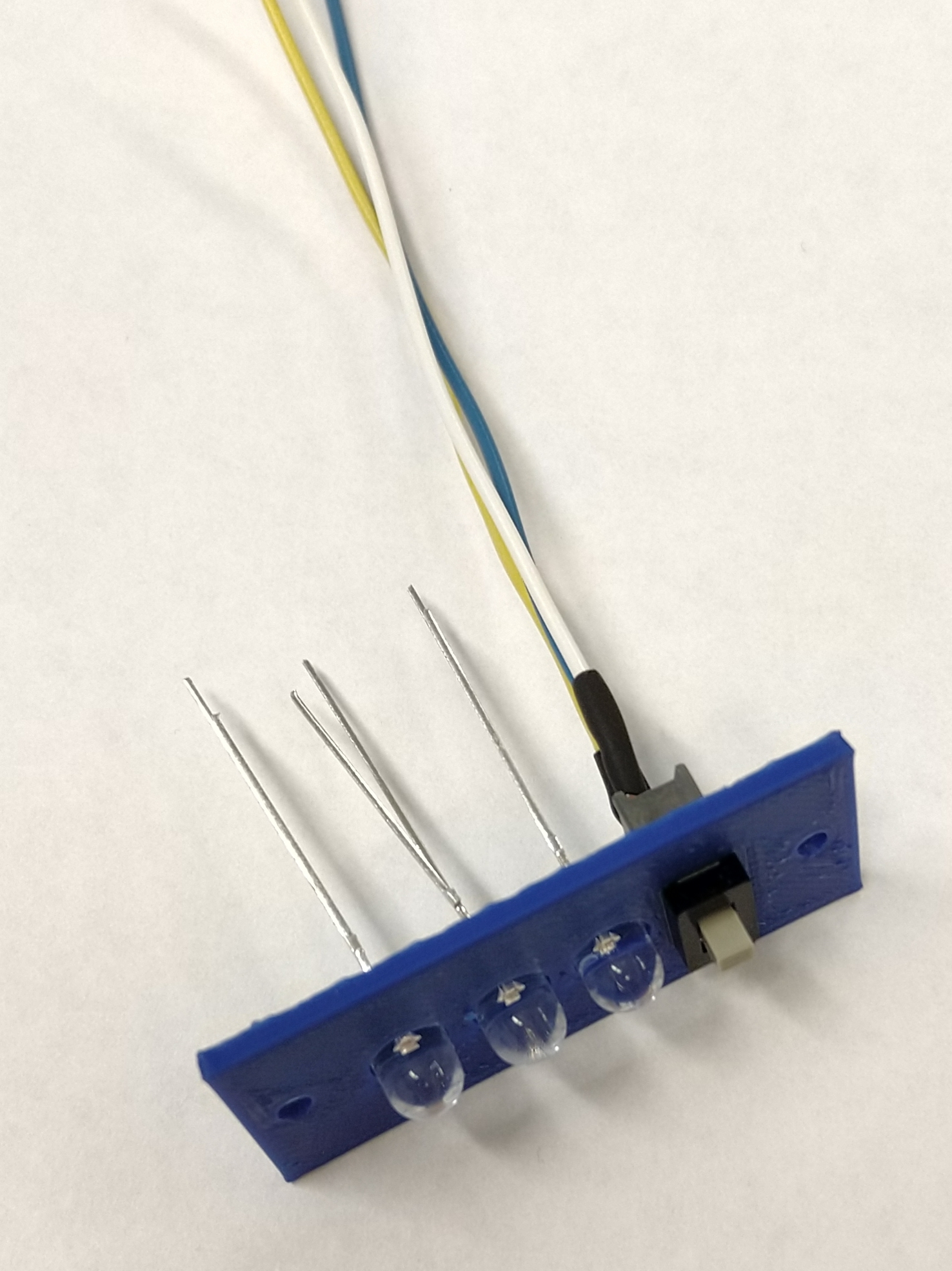
Fig. 5. Face component of the external interface with switch and LEDs inserted.
- You are now going to connect the three ground leads of the LEDs together so there is only one ground connection to the external interface. The two LEDs nearest to the switch need to have their ground legs bent so they can be soldered to the outermost LED’s ground leg. Remember to put heat shrink on before bending these legs. Now you should have three LED positive connections, one shared LED ground connection, and three switch connections as shown in Fig. 6.
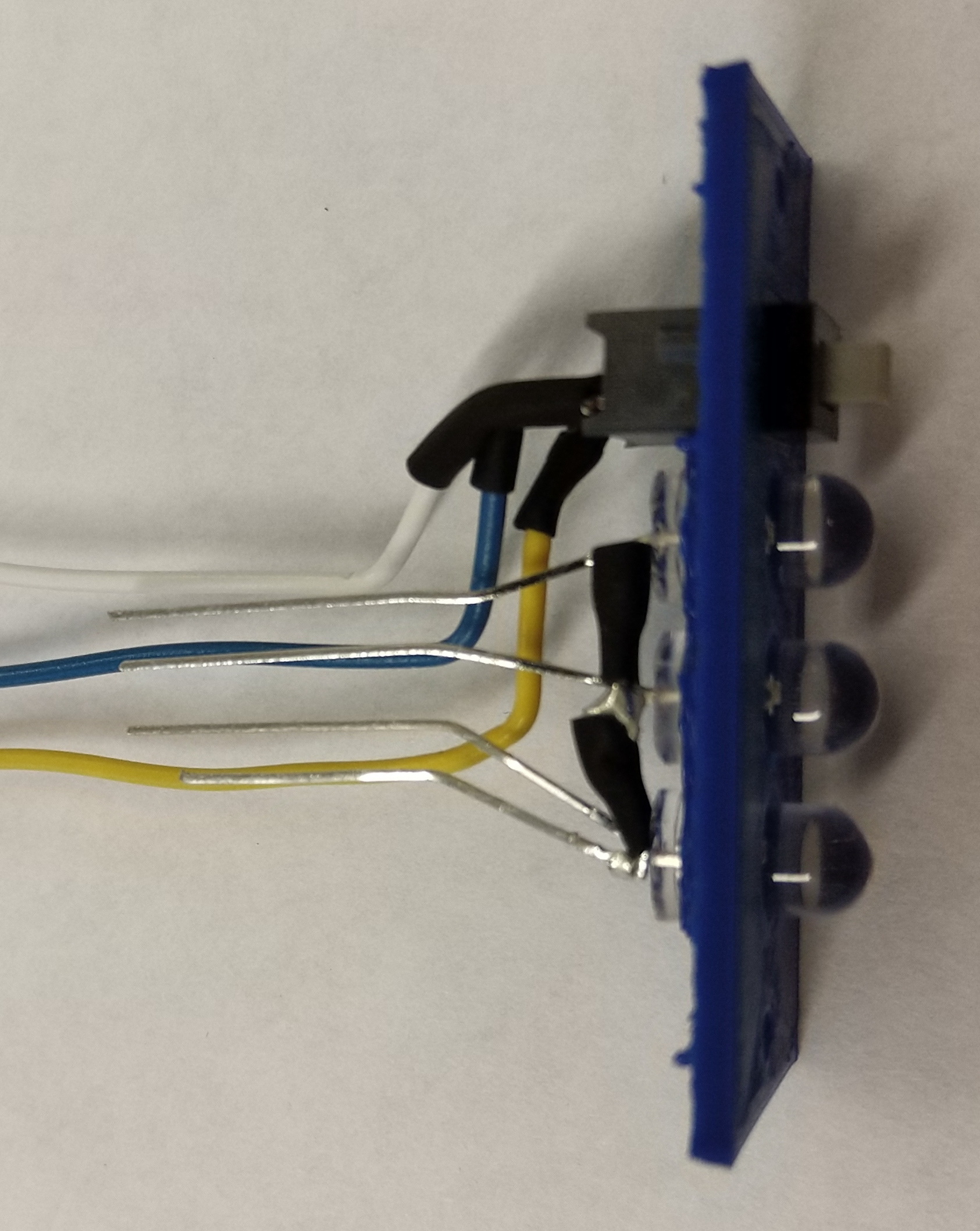
Fig. 6. The bare metal lead at the bottom of this image is the ground connection to the three LEDs (with the connections between adjacent LEDs covered in shrink tube).
- We now need to bend these 7 connections to approximately where they will be when they connect to the male IDC header. We will use the 2-by-5 perforated board piece to help align them. The following table shows where each wire will pass through the perforated board and then connect to the IDC header. The 2-by-5 header has three empty connections (labeled NC).
IDC header connections (under side view). If properly oriented the polarity notch is at the top and the ground indicator (triangle on header) is at the top left.¶ LED GND LED 1+ LED 2+ LED 3+ NC SW up NC NC SW center SW down
- Position the wires to match up with the bottom of the connector and use the perforated board piece for proper spacing. Once they are positioned, place the interface face inside the interface body, letting the wires go out the back (Fig. 7). Mark where the wires cross over the beam at the back of the body piece. You will need to cut the wires so that they do not extend beyond this beam (Fig. 8).
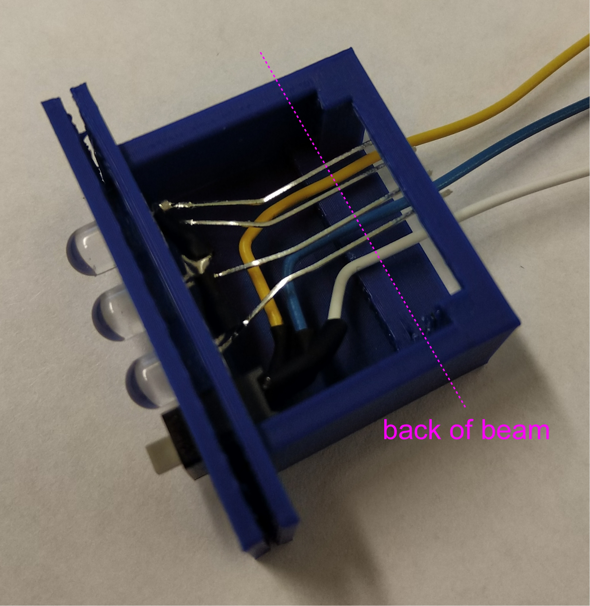
Fig. 7. Temporary assembly of face into body in order to determine where to cut wires. A beam across the back of the body will help hold the IDC header. The wires should be cut at side of the beam opposite the face, as indicated by the dashed line in the photograph.
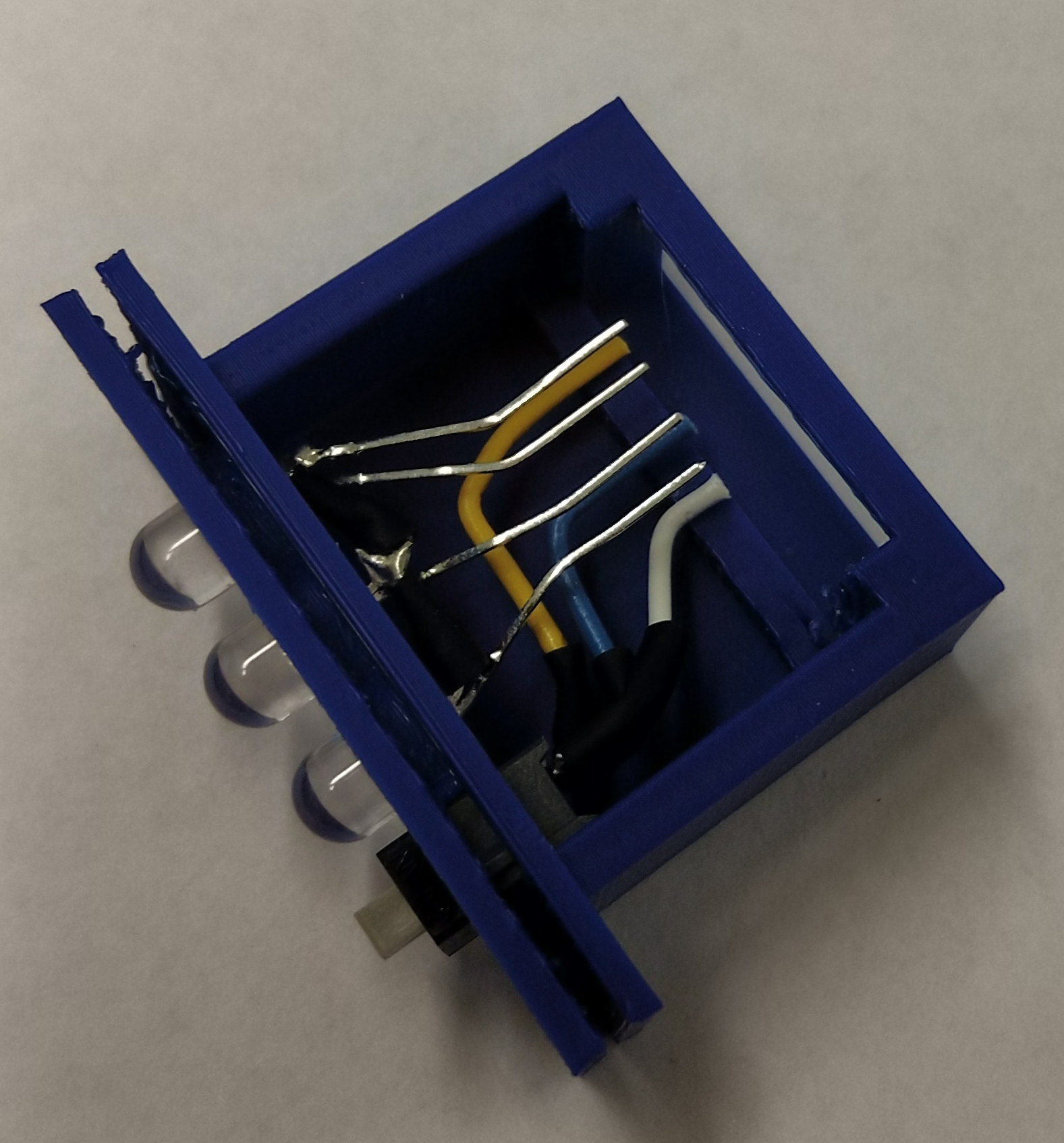
Fig. 8. Temporary assembly of face into body. Wires have now been cut to the correct length.
- Once the wires are cut and stripped, remove the face and body and then replace the perforated board piece. This piece will sit on the inner side of the beam to help secure the IDC connector. Solder on the connector, making sure the wires connect as specified in the table and shown in Fig. 9.
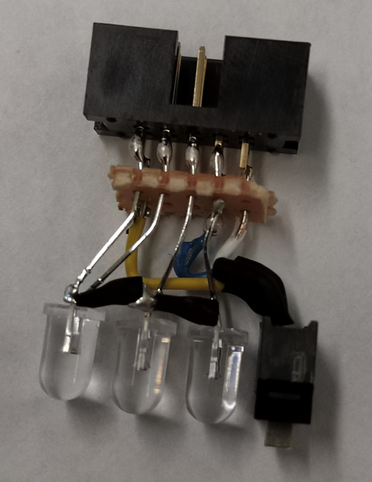
Fig. 9. Interior components of interface soldered to IDC header.
- Place the internal components inside the interface body. Push down so the IDC header is secure beyond the beam, as shown in Fig. 10. Then slide the side panel inside as well. If the panel won’t fit, the small plastic extrusion on the switch may need to be filed off. Replace the face over the switch and LEDs. It may be useful to use needle-nose pliers to pull them all the way through. The result should look like Fig. 11.
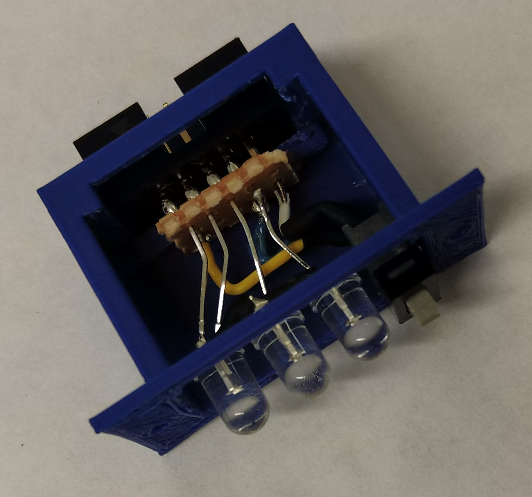
Fig. 10. Interior components placed inside of interface body.
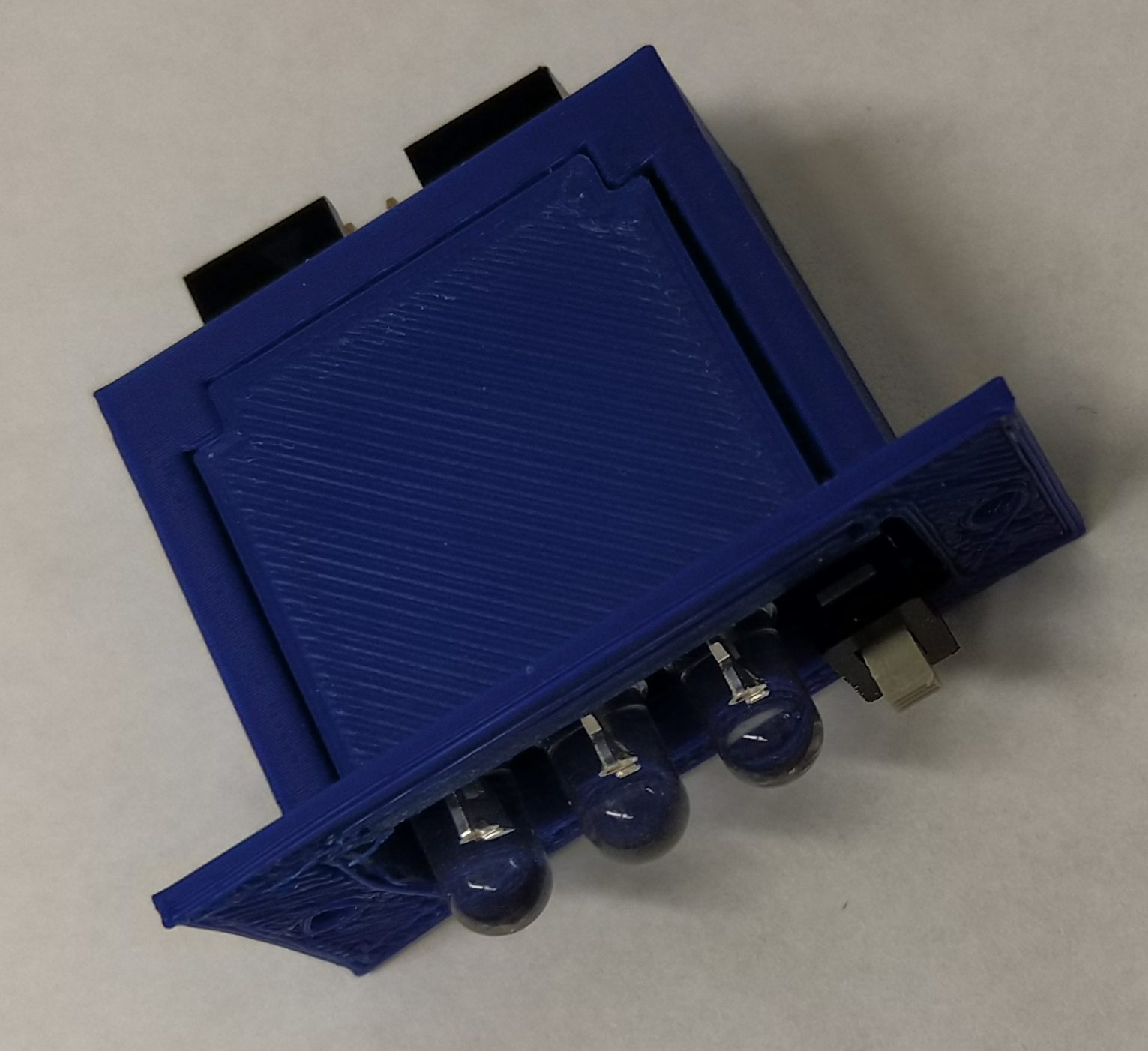
Fig. 11. Interface panel is slid into the interface body.
- Now use two 5/32-inch #2-56 screws to secure the face to the body, sealing the external interface as one piece. Fig. 12 shows the completely assembled external interface.
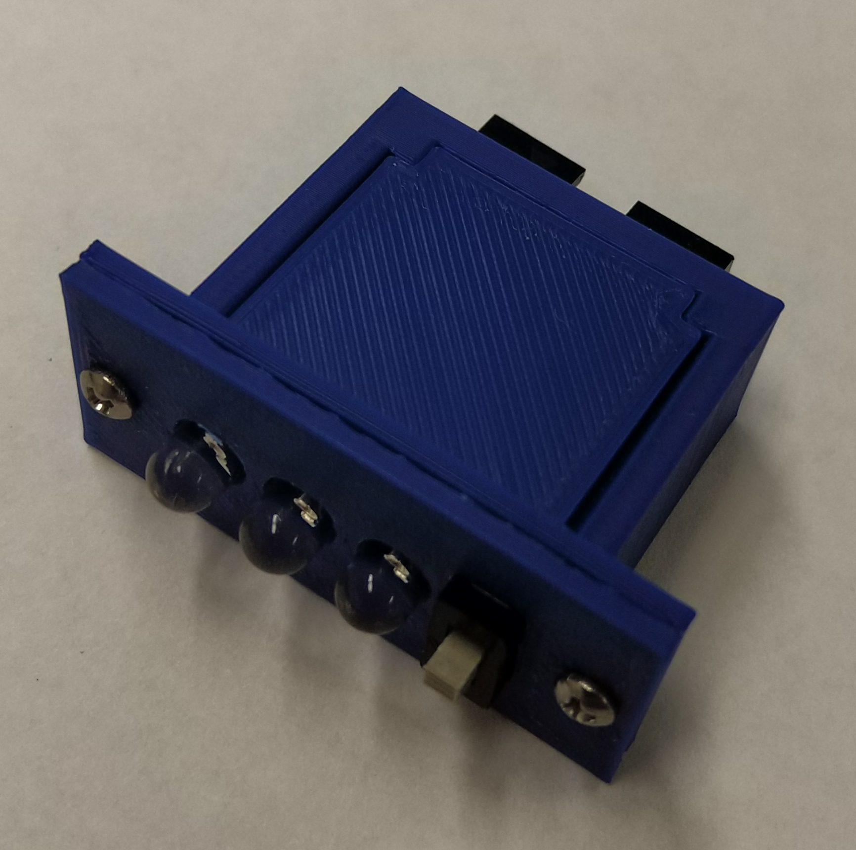
Fig. 12. Completed external interface.
4.3. Final Assembly
- The female IDC connectors need to be put on the ends of an approximately 6 inch long section of ribbon cable. The IDC receptacles must be oriented so the ground indicators (the triangle on the side) are on the same side as the red wire on the ribbon cable (see Fig. 13).
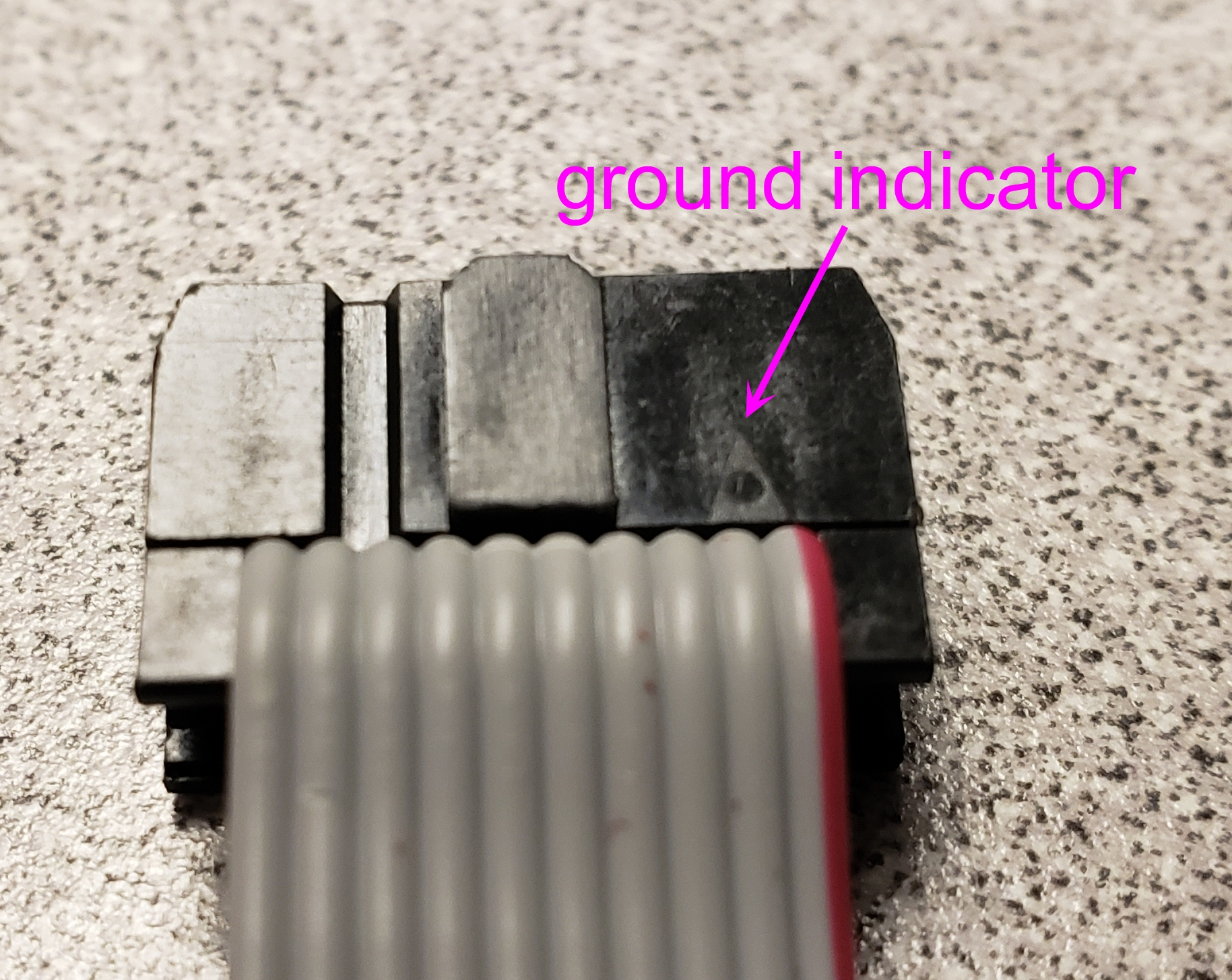
Fig. 13. The ground indicator on the IDC receptacle needs to be on the same edge as the red wire on the ribbon cable.
- Place the LPC1768 microcontroller, XBee module, and SD breakout board into the corresponding headers on the PCB.
- Connect the external interface to the PCB using the ribbon cable. The Flight Computer is now fully assembled and ready for use (see Fig. 14).
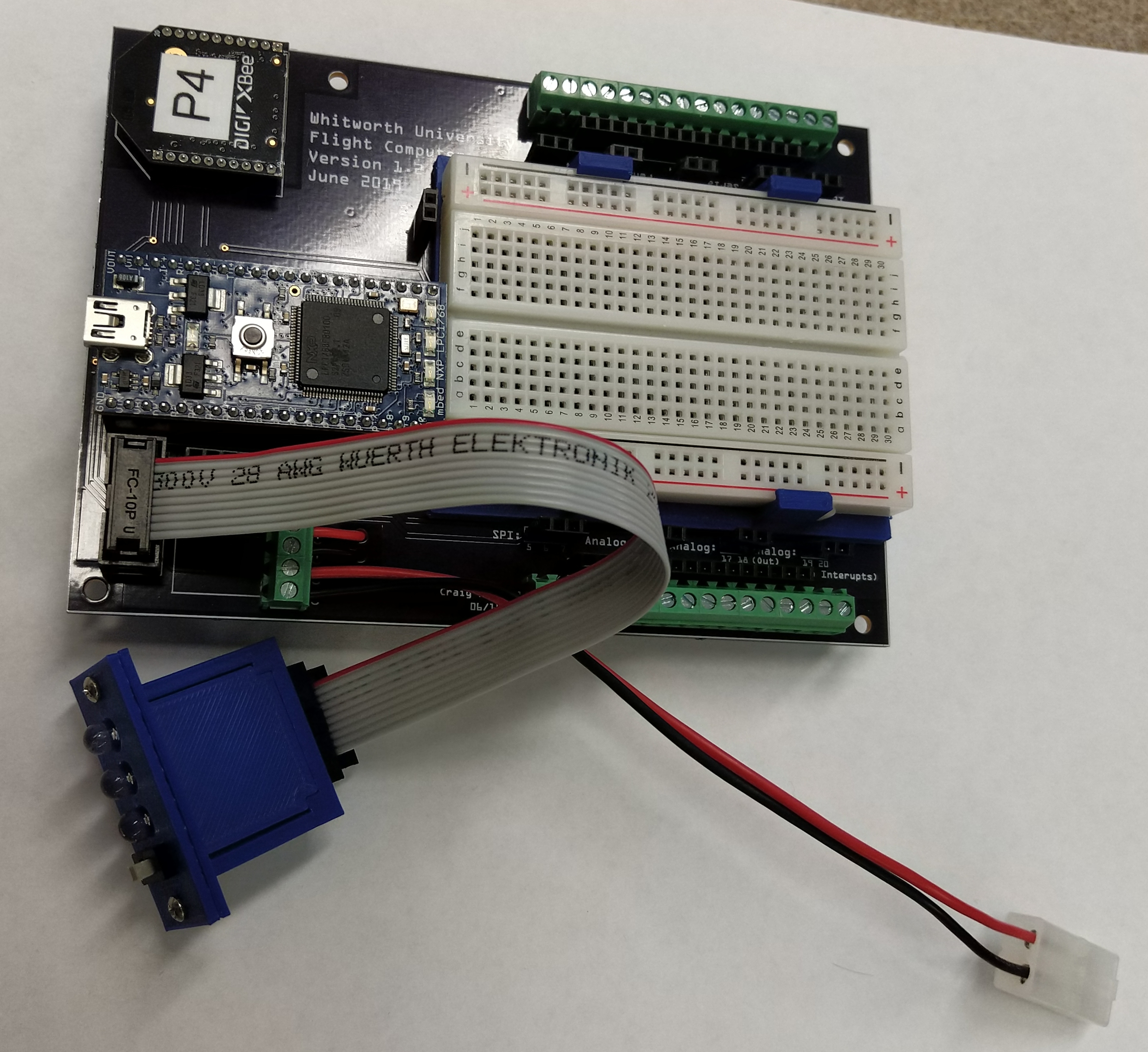
Fig. 14. Fully assembled standard Flight Computer.